Colorful LED Heart Display
Do-It-Yourself Kit with 32 Multi-Color LEDs
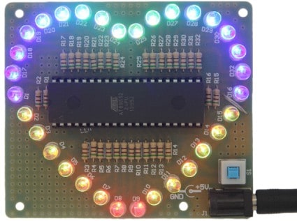
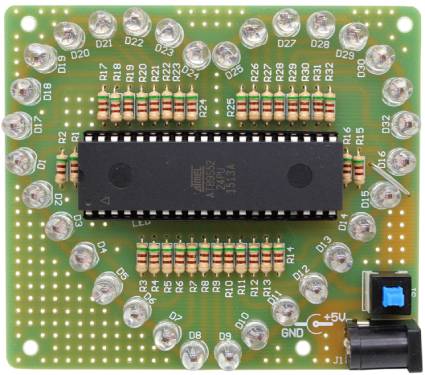
The LED Heart is a very complex, yet simple design. It incorporates 32 multi-colored LEDs in the shape of a heart. An advanced microcontroller drives various elegant and hypnotizing lighting sequences.
Available as a kit (See LED Colorful Heart Display Kit at PCBoard.ca), the assembly is possible in one evening. Power to the display is through the included USB cable. Connects an open USB port on your computer or USB charging power supply.
Each kit includes all components necessary to build the LED Heart Display. A low-wattage soldering iron with basic soldering skills will allow you to complete the package.
Downloadable User Guide
A complete user guide with instructions is available for download as a PDF document.
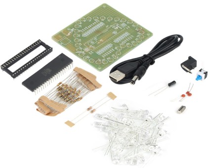
Parts Kit Includes:
Kits include all parts necessary to build the LED Heart.
Resistors:
32 x 510 ohm 1/4 watt resistor (R1-R32)
1 x 10K ohm 1/4 watt resistor (R33)
Capacitors:
2 x 22pF (C1, C2)
1 x 10uF 25v Electrolytic Capacitor (C3)
Crystal:
1 x 11Mhz – 12Mhz Crystal (Y1)
Semiconductors:
32 x Multi-color LEDs (D1-D32)
1 x 40-Pin Microcontroller (U1)
Sockets, Connectors, and Switches:
1 x 40-pin DIP Socket (U1)
1 x Power Switch (S1)
1 x Power Connector, 2.1mm (J1)
1 x USB to 2.1mm Power Cable (S1)
Main Board:
1 x Single Sided PCB
Assembly Instructions
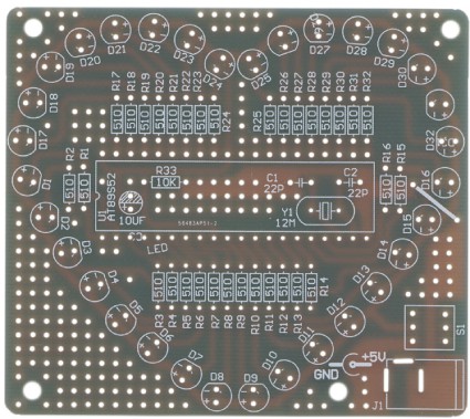
The design of the board positions several components beneath the microcontroller inside of the IC socket. This is an excellent location to begin assembling the unit.
- Install R33 (10K ohm resistor, Brown-Black-Orange
Gold) along with capacitors C1 and C2 (33pf) - Now install C3 (10uf) observing the correct polarity
and position it so that it lays on its side - The crystal, Y1, can now installed into the board
This takes care of the installation of the components under the microcontroller. Now we can move on to the rest of the board.
- There are now 32 pieces of 510-ohm resistors (Green-Brown-Brown) to install into the board at positions R1 to R32
- After installing all resistors, there is one jumper to fit on the board. Use one of the discarded legs of the resistors.
- The jumper is labeled on the board and located in the middle-right side between resistor R15 and R16 in-between D15 and D16
Now install the 32 LEDs to the board. Note that the LED has one short lead and one long. The long lead is the anode (positive) and goes into the hole on the board labeled with a + sign. Ensure the LEDs are flush to the board when installing
- Now install the power switch into position S1 along with the power jack at J1
- Install the IC socket at U1 to the board. Make note that Pin 1 of the microcontroller is located on the left side of the board. Position the device to fit onto the board around the components installed in the first steps
- This only leaves the micro controller for installation. When installing, make sure that pin one is located on the left side of the board
This completes the assembly of the board
Powering Up Your LED Heart
To power up the board, install the included cable into the power jack at J1. Plug the other end of the cable into a USB port on a computer or to a USB charger. Once connected, press the power switch S1 to power up the unit and enjoy the various sequences.
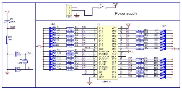
LED Heart Schematic