How To Control an I2C LCD with Arduino
How To Setup a 2×16 or 4×20 LCD Display

The Arduino family of devices is features rich and offers many capabilities. The ability to interface to external devices readily is very enticing, although the Arduino has a limited number of input/output options. Adding an external display would typically require several of the limited I/O pins. Using an I2C interface, only two connections for an LCD character display are possible with stunning professional results. We offer both 2 x 16 and 4 x 20 LCD displays.
I2C LCD Interfacing
The character LCD is ideal for displaying text and numbers and special characters. LCDs incorporate a small add-on circuit (backpack) mounted on the back of the LCD module. The module features a controller chip handling I2C communications and an adjustable potentiometer for changing the intensity of the LED backlight. An I2C LCD advantage is that wiring is straightforward, requiring only two data pins to control the LCD.
A standard LCD requires over ten connections, which can be a problem if your Arduino does not have many GPIO pins available. If you happen to have an LCD without an I2C interface incorporated into the design, these can be easily acquired separately.
The LCD displays each character through a matrix grid of 5×8 pixels. These pixels can display standard text, numbers, or special characters and can also be programmed to display custom characters easily.
How To Connect the I2C LCD to Arduino UNO
Connecting the Arduino UNO to the I2C interface of the LCD requires only four connections. The connections include two for power and two for data. The chart below shows the connections needed.

| I2C LCD Pin | Arduino UNO Pin |
|---|---|
Arduino Family Pinouts
The I2C LCD interface is compatible across much of the Arduino family. The pin functions remain the same, but the labeling of those pins might be different.
This chart will assist in identifying the pins on your Arduino model to the SDA and SCL functions.
The Arduino R3 also extends the Data Line (SDA) and Clock Line (SCL) to the header pin beside the AREF header.
| Arduino Board Model | SDA Pin | SCL Pin |
|---|---|---|
Contrast Adjust – A Necessary First Step
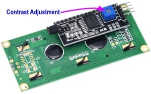 Once you have the four connections to your LCD made, you can power your Arduino, which will provide power to the LCD. The LCD has an adjustment on it which needs to be approximately set to allow you to see characters on the display. You must now adjust that contrast setting.
Located on the back of the LCD screen is the I2C interface board, and on the interface is an adjustable potentiometer. This adjustment is made with a small screwdriver. You will adjust the potentiometer until a series of rectangles appear – this will allow you to see your programming results.
After you have your first program loaded, and you can see the output on the LCD, you can go back and adjust the contrast control for optimal viewing.
Installing the LCD Library
The Arduino module and editor do not know how to communicate with the I2C interface on the LCD. The parameter to enable the Arduino to send commands to the LCD are in separately downloaded LiquidCrystal_I2C library.
The LiquidCrystal_I2C is available from GitHub. When visiting the GitHub page, select the Code button and from the drop-down menu, choose Download ZIP option to save the file to a convenient location on your workstation.
We also have the LiquidCrystal_I2C library available for download directly on our site should the master GitHub repository ever disappear.
Before installing LiquidCrystal_I2C, remove any other libraries that may reside in the Arduino IDE with the same LiquidCrystal_I2C name. Doing this will ensure that only the known good library is in use. LiquidCrystal_I2C works in combination with the preinstalled Wire.h library in the Arduino editor.
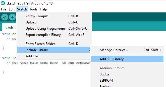
To install the LiquidCrystal_I2C library, use the SketchSketch > Include Library > Add .ZIP Library… from the Arduino IDE (see example). Point to the LiquidCrystal_I2C-master.zip which you previously downloaded and the Library will be installed and set up for use.
Several examples and code are included in the Library installation, which can provide some reference and programming examples. You can use these example sketches as a basis for developing your own code for the LCD display module.
Uninstalling The Arduino IDE
There may be situations where you should uninstall the Arduino IDE. The reason for this could be due to Library conflicts or other configuration issues. There are a few simple steps to uninstalling the IDE.
- Delete the Documents -> Arduino -> Libraries to remove all your libraries
- Delete the User -> AppData -> Local -> Arduino15 folder to remove all the preferences
- Uninstall Arduino IDE
- Install a fresh version
Determining the I2C Address of the LCD Module
Not all I2C adapters have the same or consistent I2C address. Many use the default address of 0x27, while others may use the address of 0x20.
The I2c address can be changed by shorting the address solder pads on the I2C module. You will need to know the actual address of the LCD before you can start using it.
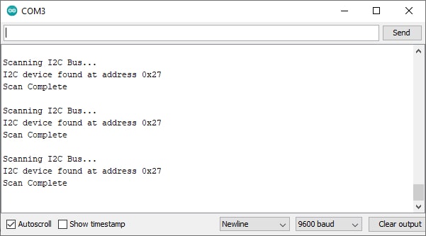
We have a simple Arduino sketch that scans the I2C bus and displays the I2C address of any devices in the serial monitor.
Use the sketch below and turn on the Serial Monitor (keyboard shortcut of Ctrl + Shift + M).
// ------------------------------------------------------------
// i2c_scanner - Updated for PCBoard.ca 2024-08-23
//
// This sketch tests the standard 7-bit addresses
// Devices with higher bit address might not be seen properly
//
// Report data is sent to Serial Monitor setup for 9600 baud
// ------------------------------------------------------------
#include <Wire.h>
void setup()
{
Wire.begin();
Serial.begin(9600);
Serial.println("\nI2C Bus Scanner");
}
void loop()
{
byte error, address;
int nDevices;
Serial.println("Scanning I2C Bus...");
nDevices = 0;
for(address = 1; address < 127; address++ )
{
// The i2c_scanner uses the return value of
// the Write.endTransmisstion to see if
// a device did acknowledge to the address.
Wire.beginTransmission(address);
error = Wire.endTransmission();
if (error == 0)
{
Serial.print("I2C device found at address 0x");
if (address<16)
Serial.print("0");
Serial.print(address,HEX);
Serial.println(" ");
nDevices++; // Increment counter for total number of devices located
}
else if (error==4)
{
Serial.print("Unknow error at address 0x");
if (address<16)
Serial.print("0");
Serial.println(address,HEX);
}
}
if (nDevices == 0)
Serial.println("No I2C devices found\n");
else
Serial.println("Scan Complete\n");
delay(4000); // wait 4 seconds before startng next scan
}
Record the I2C address displayed, as you will need it later when programming the LCD.
Hello World! – First Simple Sketch
Once you have the LCD connected and have determined the I2C address, you can proceed to write code to display on the screen. The code segment below is a complete sketch ready for downloading to your Arduino.
The code assumes the I2C address of the LCD screen is at 0x27 and can be adjusted on the LiquidCrystal_I2C lcd = LiquidCrystal_I2C(0x27,16,2); as required.
// ------------------------------------------------------------
// Hello World! Demo - Updated for PCBoard.ca 2024-08-23
//
// This sketch displays a simple message to the LCD screen
// ------------------------------------------------------------

#include <LiquidCrystal_I2C.h> // Driver Library for the LCD Module

// Wiring: Connect SDA pin to A4 and SCL pin to A5
// Connects to LCD via I2C, at address 0x27 (A0-A2 not jumpered)

LiquidCrystal_I2C lcd = LiquidCrystal_I2C(0x27,16,2); // Adjust to (0x27,20,4) for 20x4 LCD

void setup() {
  // Initiate the LCD and turn on the backlight
  lcd.init();          // Initiate the LCD module
  lcd.backlight();     // Turn on the backlight
}

void loop() {
  // Print 'Hello World!' on the first line of the LCD
  lcd.setCursor(0, 0);          // Set the cursor on the first column and first row.
  lcd.print("Hello World!");    // Print the string "Hello World!"

  lcd.setCursor(1, 1);          //Set cursor to 2nd column and 2nd row (counting starts at 0)
  lcd.print("www.PCBoard.ca");
}
Built-In Functions of the LiquidCrystal_I2C Library
clear()
This function will clear the LCD screen of any characters and positions the cursor in the upper-left corner (first row and first column).
Place this function in the setup function of your sketch to ensure that nothing is displayed on the LCD when you start your program.
// ------------------------------------------------------
//
// Clear() Demo - Updated for PCBoard.ca 2024-08-23
//
// ------------------------------------------------------

#include <LiquidCrystal_I2C.h> // Driver Library for the LCD Module
LiquidCrystal_I2C lcd(0x27, 16, 2);
void setup() {
  lcd.init(); // Initialize the LCD
  lcd.backlight(); // Turn on the LCD backlight
}
void loop() {
  lcd.clear(); // Clear the screen
  lcd.print("Hello");
  delay(1500); // Pause for 1.5 seconds
  lcd.clear(); // Clear the screen
  lcd.print("Goodbye");
  delay(3000); // Pause for 3 seconds
}
cursor()
This function turns on the LCD cursor. Displayed at the position of the next character to be printed and displays as an underscore line.
noCursor()
The function hides or turns off the cursor.
// ------------------------------------------------------
//
// cursor() Demo - Updated for PCBoard.ca 2024-08-23
//
// ------------------------------------------------------

#include <LiquidCrystal_I2C.h> // Driver Library for the LCD Module
LiquidCrystal_I2C lcd(0x27, 16, 2);
void setup() {
  lcd.init(); // Initialize the LCD
  lcd.backlight(); // Turn on the LCD backlight
  lcd.print("Hello!");
}

void loop() {
  lcd.cursor(); // Turn on the cursor underscore
  delay(500); // Pause for 0.5 seconds
  lcd.noCursor(); // Turn off the cursor
  delay(500); // Pause for 0.5 seconds
}
blink()
Similar to the cursor() function, this will create a block-style cursor. Displayed at the position of the next character to be printed and displays as a blinking rectangle.
noBlink()
The function hides or turns off the block cursor.
// ------------------------------------------------------
//
// blink() Demo - Updated for PCBoard.ca 2024-08-23
//
// ------------------------------------------------------

#include <LiquidCrystal_I2C.h> // Driver Library for the LCD Module
LiquidCrystal_I2C lcd(0x27, 16, 2);
void setup() {
  lcd.init(); // Initialize the LCD
  lcd.backlight(); // Turn on the LCD backlight
  lcd.print("Hello!");
}
void loop() {
  lcd.blink(); // Turn on the rectangle cursor
  delay(4000); // Pause for 4 seconds
  lcd.noBlink(); // Turn off the cursor
  delay(2000); // Pause for 2 seconds
}
display()
This function will enable (turn on) the LCD and displays any characters or cursors that have been printed to the display.
noDisplay()
This function turns off any characters displayed to the LCD. The text will not be cleared from the LCD memory; rather, it is turned off. The LCD will show the screen again when display() is executed.
This function can be used to flash (turn off and on) the entire display.
// ------------------------------------------------------
//
// display() Demo - Updated for PCBoard.ca 2024-08-23
//
// ------------------------------------------------------

#include <LiquidCrystal_I2C.h> // Driver Library for the LCD Module
LiquidCrystal_I2C lcd(0x27, 16, 2);
void setup() {
  lcd.init(); // Initialize the LCD
  lcd.backlight(); // Turn on the LCD backlight
  lcd.print("Display Mode");
}

void loop() {
  lcd.display(); // Turn on display
  delay(2000); // Pause for 2 seconds
  lcd.noDisplay(); // Turn off the display
  delay(1000); // Pause for 1 seconds
}
scrollDisplayLeft()
scrollDisplayRight()
These function scroll the display contents (text and cursor) one position to the left (scrollDisplayLeft()) or the right (scrollDisplayRight()).
After 40 spaces, the function will loop back to the first character. With this function in the loop part of your sketch, you can build a scrolling text function.
Scrolling text if you want to print more than 16 or 20 characters in one line then the scrolling text function is convenient. First, the substring with the maximum of characters per line is printed, moving the start column from right to left on the LCD screen. Then the first character is dropped, and the next character is displayed to the substring. This process repeats until the full string has been displayed on the screen.
// ------------------------------------------------------
//
// scrollDisplayLeft() Demo - Updated for PCBoard.ca 2024-08-23
//
// ------------------------------------------------------

#include <LiquidCrystal_I2C.h> // Driver Library for the LCD Module
LiquidCrystal_I2C lcd(0x27, 16, 2);
void setup() {
  lcd.init(); // Initialize the LCD
  lcd.backlight(); // Turn on the LCD backlight
  lcd.print("Hello!");
}

void loop() {
  lcd.scrollDisplayLeft();
  delay(300); // Pause for 300 milliseconds
}
// ------------------------------------------------------
//
// scrollDisplayRight() Demo - Updated for PCBoard.ca 2024-08-23
//
// ------------------------------------------------------

#include <LiquidCrystal_I2C.h> // Driver Library for the LCD Module
LiquidCrystal_I2C lcd(0x27, 16, 2);
void setup() {
  lcd.init(); // Initialize the LCD
  lcd.backlight(); // Turn on the LCD backlight
  lcd.print("Hello!");
}

void loop() {
  lcd.scrollDisplayRight();
  delay(300); // Pause for 300 miliseconds
}
Creating and Displaying Custom Characters
Custom Characters
The LCD driver backpack has an exciting additional feature allowing you to create custom characters (glyph) for use on the screen. Your custom characters work with both the 16×2 and 20×4 LCD units.
A custom character allows you to display any pattern of dots on a 5×8 matrix which makes up each character. You have full control of the design to be displayed.
The example code sets up eight custom characters and displays them.
To aid in creating your custom characters, there are a number of useful tools available on Internet. Here is a LCD Custom Character Generator which we have used.
// ------------------------------------------------------
//
// Custom Characters  - Updated for PCBoard.ca 2024-08-23
//
// ------------------------------------------------------


#include <LiquidCrystal_I2C.h>  // Driver Library for the LCD Module
LiquidCrystal_I2C lcd(0x27, 16, 2);
// Change to LiquidCrystal_I2C lcd(0x27, 16, 2); for 4x20 LCD


// ------------------------------------------------------
//
// Define up to 8 custom characters
//
// ------------------------------------------------------


byte Alien[] = {
  B11111,
  B10101,
  B11111,
  B11111,
  B01110,
  B01010,
  B11011,
  B00000
};

byte Bell[] = {
  B00100,
  B01110,
  B01110,
  B01110,
  B11111,
  B00000,
  B00100,
  B00000
};

byte Check[] = {
  B00000,
  B00001,
  B00011,
  B10110,
  B11100,
  B01000,
  B00000,
  B00000
};

byte Heart[] = {
  B00000,
  B01010,
  B11111,
  B11111,
  B01110,
  B00100,
  B00000,
  B00000
};

byte Lock[] = {
  B01110,
  B10001,
  B10001,
  B11111,
  B11011,
  B11011,
  B11111,
  B00000
};

byte Skull[] = {
  B00000,
  B01110,
  B10101,
  B11011,
  B01110,
  B01110,
  B00000,
  B00000
};

byte Note[] = {
  B00001,
  B00011,
  B00101,
  B01001,
  B01001,
  B01011,
  B11011,
  B11000
};

byte Speaker[] = {
  B00001,
  B00011,
  B01111,
  B01111,
  B01111,
  B00011,
  B00001,
  B00000
};

void setup() {
  lcd.init();      // Initialize the LCD
  lcd.backlight(); // Turn on the LCD backlight


// ------------------------------------------------------
//
// Move the designs into the Character Buffer for each character
//
// ------------------------------------------------------


  lcd.createChar(0, Alien);
  lcd.createChar(1, Bell);
  lcd.createChar(2, Check);
  lcd.createChar(3, Heart);
  lcd.createChar(4, Lock);
  lcd.createChar(5, Skull);
  lcd.createChar(6, Note);
  lcd.createChar(7, Speaker);

  lcd.clear(); // Clear the LCD screen of anything

  lcd.print("Custom Character");
}

// ------------------------------------------------------
//
// Display the eight custom characters
//
// ------------------------------------------------------

void loop() {
  lcd.setCursor(0, 1);
  lcd.write(0);

  lcd.setCursor(2, 1);
  lcd.write(1);

  lcd.setCursor(4, 1);
  lcd.write(2);

  lcd.setCursor(6, 1);
  lcd.write(3);

  lcd.setCursor(8, 1);
  lcd.write(4);

  lcd.setCursor(10, 1);
  lcd.write(5);

  lcd.setCursor(12, 1);
  lcd.write(6);

  lcd.setCursor(14, 1);
  lcd.write(7);
}