NodeMCU IoT Experimenter Prototype Board
Prototyping Platform for NodeMCU ESP8266 IoT Processors
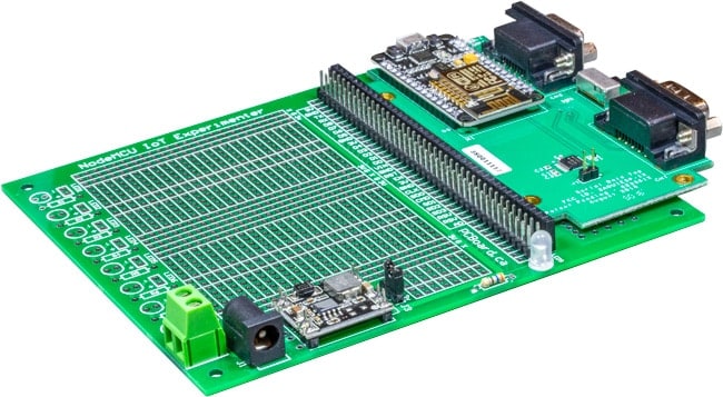
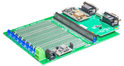
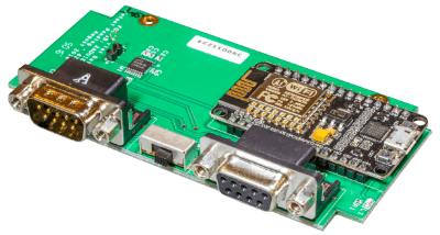
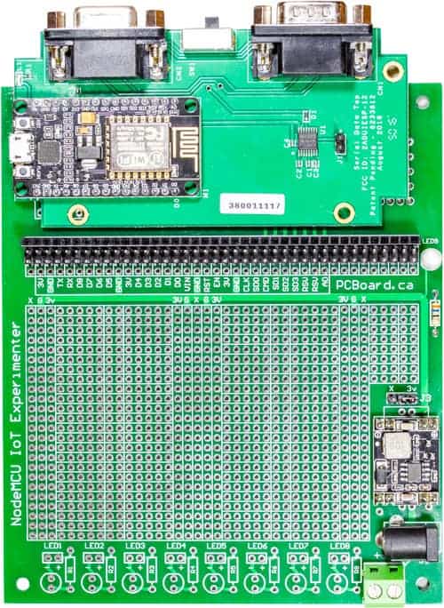
The NodeMCU IoT Experimenter is a versatile prototyping platform for use with a variety of the most popular NodeMCU modules including our NodeMCU carrier board. Great to use for IoT projects, advanced or straightforward interfacing, and as a prototyping platform. The NodeMCU, with its versatility, including its ability to be programmed and used from the Arduino IDE, makes it along with this prototyping board the perfect experimenter’s solution.
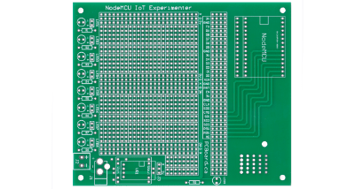
The NodeMCU IoT Experimenter measures 5 5/16” x 4.5” (135mm x 115mm) with a solder mask on each side, plated holes along with a high-contrast silk-screen labeling component, and prototyping positions.
Features of the board include a mounting socket area to accept either wide 1.1″ or narrow 0.9″ pitch NodeMCU modules. This includes the Amica NodeMCU carrier board (narrow pin spacing) to compatible variants such as the LoLin NodeMCU models. Power can be provided directly to your NodeMCU module through its built-in USB interface. Alternately, power can be supplied to the NodeMCU IoT Experimenter board which has provisions for a regulated power supply module.
The board offers over 1,000 plated-through holes on the prototype surface, mounting for eight status indicator LEDs along with dropping resistors and a power indicator LED. The prototyping area offers power busbars for the Ground (G), +3.3V (3V) power rail, and a third rail X. The third rail can be used for external voltages such as a 5V rail.
Interfacing to the NodeMCU is through a series of headers that extend each pin of the NodeMCU to rows of four headers. Each port is labeled to identify matching pins from the NodeMCU. The header area is located below the NodeMCU using standard 40-pin headers allowing for versatility in interfacing for sockets or header pins.
Options For Ordering the NodeMCU IoT Experimenter
Parts List and Placement Guide
Component List
Processor:
[ ] (1) NodeMCU Processor – NodeMCU
Supports 0.9” or 1.1” pitch NodeMCU
Semiconductors (LEDs and Regulator):
[ ] (8) Blue Indicator LED – LED1-LED8
[ ] (1) Blue Indicator LED – LED9
[ ] (1) Regulator Module (3.3V) – see details – VR1
Resistors (1/4 watt, 5% Carbon Film):
[ ] (8) Current limiting resistor – see note below – R1-R8
[ ] (1) 75Ω (violet-green-black-gold) – R9
Sockets, Headers, and Connectors:
[ ] (1) 2.1mm or 2.5mm Coaxial Jack PCB Mount – J1
[ ] (1) Rising Clamp Terminal Block (2 position) – J2
[ ] (1) 3-pin Single Row Header & Shorting Block – J3
[ ] (1) 40-pin Female Connector – I/O Connector
[ ] (1) Dual Row 40-pin Male Connector – I/O Connector
User Guide
We have a print version of the NodeMCU IoT Experimenter board available for download. It contains the necessary information and details needed to build your own board.
NodeMCU Processor Notes
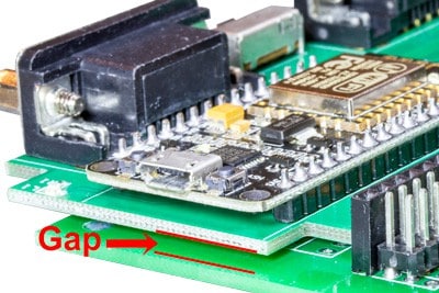
When installing the NodeMCU carrier module, leave a small gap of 1/16”-1/8” (2-3mm) between the bottom of the processor carrier and the NodeMCU IoT Experimenter. This ensures traces from the processor board do not short against traces on the mainboard.
Regulated Power Module
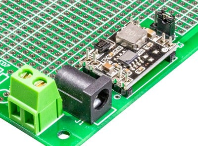
Located above the regulator module is a 3-way jumper at J3 and offers two positions, X or 3V. When jumpered across the Center Pin to 3V, the output from the regulator module will be provided to the NodeMCU and 3V rails on the board.
Alternately, if you install a different value of regulator (such as a 5V model), position the jumper across the Center Pin and X which will direct the current to the X rails on the board.
If using a higher value regulator than 3.3V (such as a 5V), the regulator on the NodeMCU can be used to power the NodeMCU. Enable the jumper to X position (which provides power to the X rails). Place a jumper from any X rail to Vin interface pad. Keep in mind; you will be limited to the current handling capabilities of the regulator on the NodeMCU.
Power J3 Jumper
The NodeMCU includes an onboard AMS1117 3.3V voltage regulator. This is sufficient to power the module, but when interfacing with external circuits, it may not be adequate.
The NodeMCU IoT Experimenter features the capabilities of adding a more efficient and powerful regulator. We have chosen a cost-efficient module to go on the board at VR1 which can supply up to 3A at 3.3V.
It is advisable to solder the eight header pins on the NodeMCU IoT Experimenter.
Afterward, install a 3.3V power module onto the pins and solder into position. Ensure you match the input and output terminals to those on the board (the Input to the module should be closest to the power jacks at J1 and J2).
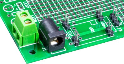
Power Input Jacks
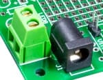 When using the optional regulated power module VR1, the board can have power applied to J1, which can be a 2.1mm or 2.5mm power jack. Connection J2 optionally accepts wires directly into the board or through a Rising Clamp Terminal Block (2-pin).
Prototype Area
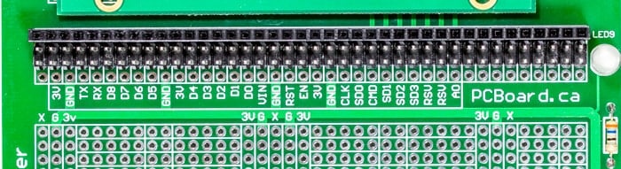
The prototype area on the board has over 1,000 plated 0.1” spaced holes. All processor pins extend to a set of four rows just below the NodeMCU and are labeled with their corresponding functions.
The top row will contain a single-row header socket that mates with Dupont-style Male connectors. The next two rows are Male header pins that mate to Dupont-style Female connectors. The last and bottom row is left empty to allow for solder connections for a more permanent solution.
LED Interface
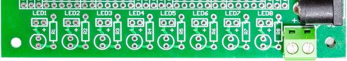
An area for eight LEDs and dropping resistors is included at the bottom of the board to aid in rapid prototyping.
Positions LED1 to LED8 offer mounts for eight LEDs along with dropping resistors (R1 to R8) for each LED. Connection to each LED is through the header block just above each LED, marked with a + and – negative connections.
When controlling LEDs from the NodeMCU, remember the NodeMCU can source or sink 12mA per pin. Select from the chart the LED color and matching series resistor below to maintain a safe current below 12mA.
White, Blue or Green LED: 75 W 1/4 watt resistor
Red, Yellow, or Orange LED: 180 W 1/4 watt resistor
Identify LED Pins Positive and Negative (Anode or Cathode)
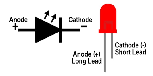
An LED has a positive (Anode) lead and a negative (Cathode) lead. The schematic symbol of the LED is similar to the diode except for two arrows pointing outwards. The Anode (+) is marked with a triangle, and the Cathode (-) is marked with a line.
The longer lead of an LED is generally the positive (Anode), while the shorter lead is the negative (cathode).
NodeMCU Compatibility with Arduino IDE
The NodeMCU offers a variety of development environments, including compatibility with the Arduino IDE (Integrated Development Environment). The NodeMCU/ESP8266 community took the IDE selection a step further by creating an Arduino add-on. If you’re just getting started programming the ESP8266 or even an established developer, this is the highly recommended environment. Visit our dedicated page on setting up and configuring the Arduino IDE for a NodeMCU ESP8266.