Proto Arduino – DIY Prototype Board
Arduino Nano or ATTiny85 Prototype Board
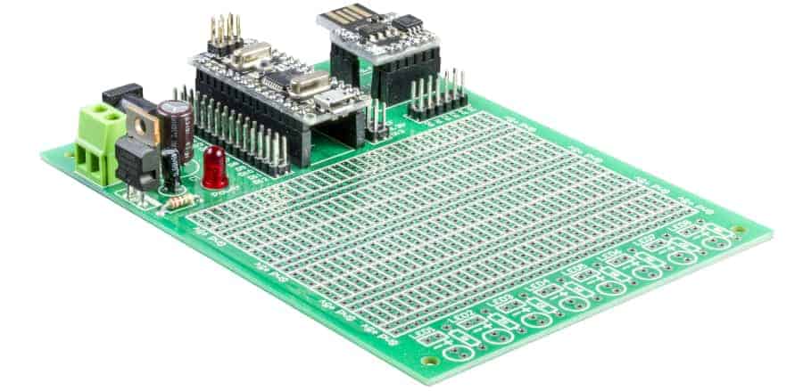
The Proto Arduino is a general-purpose prototyping platform. It is compatible with the Arduino Nano v3 or Digispark style ATTiny85 processors boards. Onboard features include a regulated power supply. Dedicated mounting provided for either an Arduino Nano or ATTiny85 processor board. The prototyping surface offers over 850 plated-through holes. Mounting for eight LEDs along with dropping resistors is also provided.
The Proto Arduino is a high-quality prototype board with solder masks on both sides of the board. Plated holes along with a high-contrast silk-screen labeling component positions. Board size is 3 3/4” x 5” (95mm x 127mm) ready to fit into standard-size project cases.
The complete Proto Arduino Users Guide is available for download in PDF format.
The Proto Arduino is available with only the base PC board or with a full kit of components.
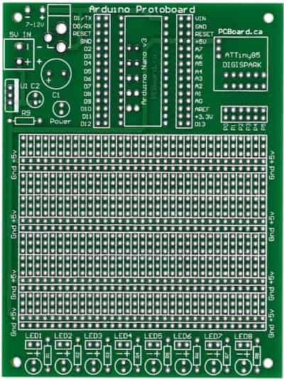
Proto Arduino Parts List
Resistor 1/4 watt, 5% Carbon Film:
[ ] (1) 220 Ω (red-red-brown-gold) R9
Capacitors:
[ ] (1) 100 uF 35v C1
[ ] (1) 10 uF 25v C2
Semiconductors:
[ ] (1) LM7805 – 5-volt regulator TO-220 Case U1
[ ] (1) Red 5mm LED Power Indicator Power
[ ] (1) Arduino Nano v3 Processor
[ ] (1) Arduino ATTiny85 Processor
Sockets, Headers, Connectors:
[ ] (2) 15-pin Female Header Nano Socket
[ ] (2) 6-pin Female Header ATTiny85 Socket
[ ] (1) 3-pin Female Header ATTiny85 Socket
[ ] (1) 2.1mm or 2.5mm Coaxial Jack PCB Power
[ ] (2) 15-pin Dual Row Male Headers
[ ] (1) 6-pin Dual Row Male Headers
Optional:
[ ] (8) Resistor R1 to R8
[ ] (8) LED (3mm or 5mm) LED1 to LED8
Optional 8-LED Display
At the bottom of the board, there are provisions for up to eight LEDs and dropping resistors. LED1 to LED8 can either be 3mm or 5mm LEDs. The dropping resistor should be 120Ω for White, Blue, Purple, or Green LEDs. For Red or Orange LEDs, the dropping resistor should be 220Ω, 1/4 watt.
On-Board Power Supply
Both the ATTiny85 and the Nano processors support a regulated 5v DC power input. They also offer the ability for a power input with a 7 to 12v DC power source. 5v DC can be applied to the “5V In” connections on the board. 7 to 12v DC is applied to the board at either the power jack or to the “7-12v” power input port. When 7-12v power is used, the regulators on the processor boards will regulate the power. It should be noted that the onboard regulators are for low current operations. The Proto Arduino board also has an onboard regulator and power filtering circuit. When this is used, the board will provide regulated 5v to both processor sockets.
On-Board Power Indicator
A LED for power indicating is included on the board. Resistor R9 limits current flow through the LED. Although a handy option, the LED draws approximately 20mA of current. The LED will illuminate when 5v power is available to either Arduino module. It will also light when the onboard 5v power supply is used.
Precautions When Assembling The Board
The 3, 6, and 15 pin connectors for the processors can deform when soldering to the board. The cause of this is the heat required to solder them into place. Apply the connectors to the processor when soldering into the board. This will keep the pins and connector body straight during the installation process.
ATTiny85 Mounting Consideration
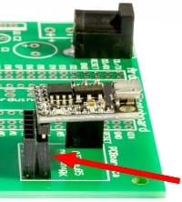 The Proto Arduino design allows for use with many manufacturers of ATTiny85 boards. Some designs have strayed from the original specifications. The pin spacing for the signal leads on the board can vary between various manufacturers. This variance can impede the installation into the protoboard socket.
This can be overcome by slightly tipping the pins towards the bottom of the protoboard. This solution has allowed us the flexibility to install all design variations in ATTiny85 boards. This should be done when you are soldering the connector to the PCB.