NodeMCU ESP8266 Detailed Review
Specifications, Overview and Setting Up Your NodeMCU
What is NodeMCU?
 The NodeMCU (Node MicroController Unit) is an open-source software and hardware development environment built around an inexpensive System-on-a-Chip (SoC) called the ESP8266. The ESP8266, designed and manufactured by Espressif Systems, contains the crucial elements of a computer: CPU, RAM, networking (WiFi), and even a modern operating system and SDK. That makes it an excellent choice for Internet of Things (IoT) projects of all kinds.
However, as a chip, the ESP8266 is also hard to access and use. You must solder wires, with the appropriate analog voltage, to its pins for the simplest tasks such as powering it on or sending a keystroke to the “computer” on the chip. You also have to program it in low-level machine instructions that can be interpreted by the chip hardware. This level of integration is not a problem using the ESP8266 as an embedded controller chip in mass-produced electronics. It is a huge burden for hobbyists, hackers, or students who want to experiment with it in their own IoT projects.
But, what about Arduino? The Arduino project created an open-source hardware design and software SDK for their versatile IoT controller. Similar to NodeMCU, the Arduino hardware is a microcontroller board with a USB connector, LED lights, and standard data pins. It also defines standard interfaces to interact with sensors or other boards. But unlike NodeMCU, the Arduino board can have different types of CPU chips (typically an ARM or Intel x86 chip) with memory chips, and a variety of programming environments. There is an Arduino reference design for the ESP8266 chip as well. However, the flexibility of Arduino also means significant variations across different vendors. For example, most Arduino boards do not have WiFi capabilities, and some even have a serial data port instead of a USB port.
NodeMCU Specifications
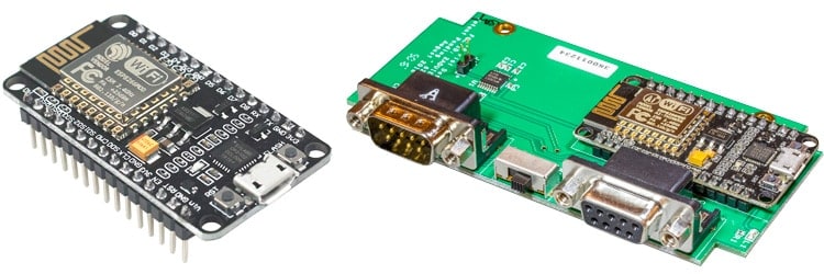
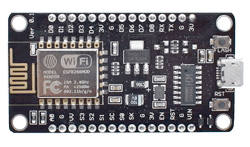
The NodeMCU is available in various package styles. Common to all the designs is the base ESP8266 core. Designs based on the architecture have maintained the standard 30-pin layout. Some designs use the more common narrow (0.9″) footprint, while others use a wide (1.1″) footprint – an important consideration to be aware of.
The most common models of the NodeMCU are the Amica (based on the standard narrow pin-spacing) and the LoLin which has the wider pin spacing and larger board. The open-source design of the base ESP8266 enables the market to design new variants of the NodeMCU continually.
Official Amica
NodeMCU
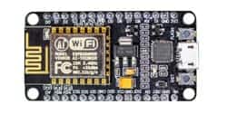
Amica NodeMCU measures 49mm x 26mm with a standard pin space of 0.1″ between pins and 0.9″ between rows.
The Amica NodeMCU is approximately 25% smaller in size than a closely compatible LoLin style NodeMCU
Official Amica NodeMCU
on Carrier Board
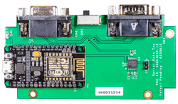
Amico NodeMCU mounted to a 102mm x 51mm carrier board with dual DB-09 male/female connectors
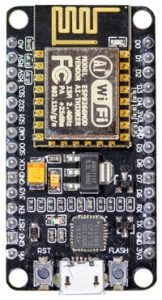
Lolin
NodeMCU
LoLin style NodeMCU measures 58mm x 32mm with a pin spacing of 0.1″ between pins and 1.1″ between rows
NodeMCU Technical Specifications
| Official NodeMCU | NodeMCU Carrier Board | LoLin NodeMCU | |
|---|---|---|---|
| Microcontroller | ESP-8266 32-bit | ESP-8266 32-bit | ESP-8266 32-bit |
| NodeMCU Model | Amica | Amica | Clone LoLin |
| NodeMCU Size | 49mm x 26mm | 49mm x 26mm | 58mm x 32mm |
| Carrier Board Size | n/a | 102mm x 51mm | n/a |
| Pin Spacing | 0.9" (22.86mm) | 0.9" (22.86mm) | 1.1" (27.94mm) |
| Clock Speed | 80 MHz | 80 MHz | 80 MHz |
| USB to Serial | CP2102 | CP2102 | CH340G |
| USB Connector | Micro USB | Micro USB | Micro USB |
| Operating Voltage | 3.3V | 3.3V | 3.3V |
| Input Voltage | 4.5V-10V | 4.5V-10V | 4.5V-10V |
| Flash Memory/SRAM | 4 MB / 64 KB | 4 MB / 64 KB | 4 MB / 64 KB |
| Digital I/O Pins | 11 | 11 | 11 |
| Analog In Pins | 1 | 1 | 1 |
| ADC Range | 0-3.3V | 0-3.3V | 0-3.3V |
| UART/SPI/I2C | 1 / 1 / 1 | 1 / 1 / 1 | 1 / 1 / 1 |
| WiFi Built-In | 802.11 b/g/n | 802.11 b/g/n | 802.11 b/g/n |
| Temperature Range | -40C - 125C | -40C - 125C | -40C - 125C |
| Product Link | NodeMCU | NodeMCU |
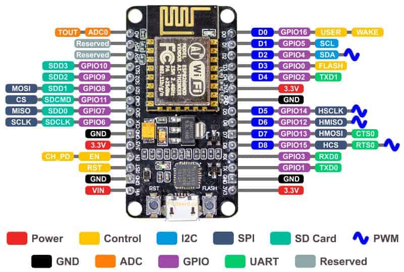
NodeMCU Pinout and Functions Explained
-
- Power Pins There are four power pins. VIN pin and three 3.3V pins.
- VIN can be used to directly supply the NodeMCU/ESP8266 and its peripherals. Power delivered on VIN is regulated through the onboard regulator on the NodeMCU module – you can also supply 5V regulated to the VIN pin
- 3.3V pins are the output of the onboard voltage regulator and can be used to supply power to external components.
- Power Pins There are four power pins. VIN pin and three 3.3V pins.
-
- GND are the ground pins of NodeMCU/ESP8266
-
- I2C Pins are used to connect I2C sensors and peripherals. Both I2C Master and I2C Slave are supported. I2C interface functionality can be realized programmatically, and the clock frequency is 100 kHz at a maximum. It should be noted that I2C clock frequency should be higher than the slowest clock frequency of the slave device.
-
- GPIO Pins NodeMCU/ESP8266 has 17 GPIO pins which can be assigned to functions such as I2C, I2S, UART, PWM, IR Remote Control, LED Light and Button programmatically. Each digital enabled GPIO can be configured to internal pull-up or pull-down, or set to high impedance. When configured as an input, it can also be set to edge-trigger or level-trigger to generate CPU interrupts.
-
- ADC Channel The NodeMCU is embedded with a 10-bit precision SAR ADC. The two functions can be implemented using ADC. Testing power supply voltage of VDD3P3 pin and testing input voltage of TOUT pin. However, they cannot be implemented at the same time.
-
- UART Pins NodeMCU/ESP8266 has 2 UART interfaces (UART0 and UART1) which provide asynchronous communication (RS232 and RS485), and can communicate at up to 4.5 Mbps. UART0 (TXD0, RXD0, RST0 & CTS0 pins) can be used for communication. However, UART1 (TXD1 pin) features only data transmit signal so, it is usually used for printing log.
-
- SPI Pins NodeMCU/ESP8266 features two SPIs (SPI and HSPI) in slave and master modes. These SPIs also support the following general-purpose SPI features:
- 4 timing modes of the SPI format transfer
- Up to 80 MHz and the divided clocks of 80 MHz
- Up to 64-Byte FIFO
- SPI Pins NodeMCU/ESP8266 features two SPIs (SPI and HSPI) in slave and master modes. These SPIs also support the following general-purpose SPI features:
-
- SDIO Pins NodeMCU/ESP8266 features Secure Digital Input/Output Interface (SDIO) which is used to directly interface SD cards. 4-bit 25 MHz SDIO v1.1 and 4-bit 50 MHz SDIO v2.0 are supported.
-
- PWM Pins The board has 4 channels of Pulse Width Modulation (PWM). The PWM output can be implemented programmatically and used for driving digital motors and LEDs. PWM frequency range is adjustable from 1000 μs to 10000 μs (100 Hz and 1 kHz).
-
- Control Pins are used to control the NodeMCU/ESP8266. These pins include Chip Enable pin (EN), Reset pin (RST) and WAKE pin.
- EN: The ESP8266 chip is enabled when EN pin is pulled HIGH. When pulled LOW the chip works at minimum power.
- RST: RST pin is used to reset the ESP8266 chip.
- WAKE: Wake pin is used to wake the chip from deep-sleep.
- Control Pins are used to control the NodeMCU/ESP8266. These pins include Chip Enable pin (EN), Reset pin (RST) and WAKE pin.
-
 Control Pins are used to control the NodeMCU/ESP8266. These pins include Chip Enable pin (EN), Reset pin (RST) and WAKE pin.
- EN: The ESP8266 chip is enabled when EN pin is pulled HIGH. When pulled LOW the chip works at minimum power.
- RST: RST pin is used to reset the ESP8266 chip.
- WAKE: Wake pin is used to wake the chip from deep-sleep.
USB to Serial Converter – CP2102 or CH340G
Incorporated into each NodeMCU is a USB to Serial Converter. The official design is based on the CP2102 chipset and offers the best compatibility. Genuine boards use the CP2102 chipset including the officially licensed Amica NodeMCU modules. The other common USB to Serial Converter used is the CH340G which is common on the lower-priced modules including the LoLin units. Other designs may use drivers including the FTDI chipset, but those designs are rare.
Depending on the Operating System you are using with the NodeMCU, the appropriate driver must be installed. Generally, Windows 10 immediately recognizes the CP2102 chipset while the CH340G may require separate installation.
 Drivers for the CP2102 are available for download from the Silicon Labs support site. Drivers constantly evolve and ensuring and installing the most recent version in your development environment minimum issues. Drivers are available for Windows, Mac, Linux, and Android. We also have a local copy of the CP2102 drivers (v10.1.8) available locally for download. You are always best to visit the original manufacturer to ensure you are receiving the most recent versions of the driver.
 Drivers for the CP2102 are available for
 - WCH maintain and update the drivers for the CH340G on a regular basis. Versions of the driver are also available for Windows, Mac, Linux, and Android. Visit their Driver Download page. We also have a local copy of the CH340G drivers (version 3.5) available locally for download. You are always best to visit the original manufacturer to ensure you are receiving the most recent versions of the driver.
 WCH maintain and update the drivers for the CH340G on a regular basis. Versions of the driver are also available for Windows, Mac, Linux, and Android. Visit their
 We have experienced situations where both CP2102 and CH340G devices have not functioned or been recognized as expected. The solution was as simple as uninstalling the old driver and installing the most recent version.
NodeMCU Compatibility with Arduino IDE
The NodeMCU offers a variety of development environments, including compatibility with the Arduino IDE (Integrated Development Environment). The NodeMCU/ESP8266 community took the IDE selection a step further by creating an Arduino add-on. If you’re just getting started programming the ESP8266 or even an established developer, this is the highly recommended environment. Visit our dedicated page on setting up and configuring the Arduino IDE for a NodeMCU ESP8266.
NodeMCU Carrier Board
NodeMCU Carrier Board with Serial Ports
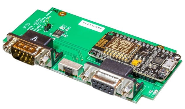
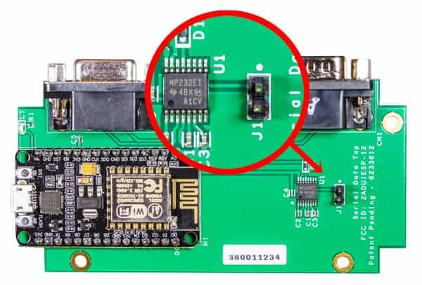
The NodeMCU Carrier Board features a genuine Amica NodeMCU ESP8266 processor along with a DB09 male and female connector with an RS-232 level converter.
The original design of the Carrier Board was for a WiFi application and the serial ports allowed for RS-232 data to be provided over the serial connectors, through a MAX232 compatible level converter to the NodeMCU. The level converter allows true RS-232 signals to be sent to the NodeMCU without worrying about the wide voltage swings.
NodeMCU Carrier Board Schematic
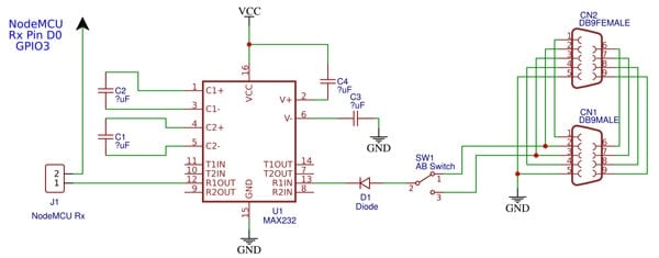
The NodeMCU Carrier Board schematic shows the two DB-09 connectors, along with the switch at SW1. The switch toggles the data from either DB-09 between Pin 2 or Pin 3 to the level converter.
Finally, there is a jumper position at J1. The allows serial data from either DB-09 to appear on the NodeMCU Rx pin.
It is important to note that with a jumper placed across J1, this will interfere with the ability of the USB connector on the NodeMCU module, in particular, the ability to program the NodeMCU. If programming/reprogramming the NodeMCU, it is advisable to remove the jumper when programming.
NodeMCU ESP8266 IoT Experimenter
NodeMCU Development and Prototyping Platform
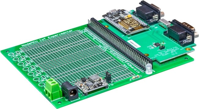
What Is The NodeMCU IoT Experimenter?
The NodeMCU IoT Experimenter is a versatile prototyping platform for use with a variety of the most popular NodeMCU modules including our NodeMCU Carrier Board. Great to use for IoT projects, advanced or straightforward interfacing, and as a prototyping platform. The NodeMCU, with its versatility, including its ability to be programmed and used from the Arduino IDE, makes it along with this prototyping board the perfect experimenter’s solution.
The NodeMCU IoT Experimenter measures 5 5/16″ x 4.5″ (135mm x 115mm) with a solder mask on each side, plated holes along with a high-contrast silk-screen labeling component and prototyping positions.
Features of the board include a mounting socket area to accept either wide 1.1″ or narrow 0.9″ pitch NodeMCU modules. This includes the Amica NodeMCU carrier board (narrow pin spacing) to compatible variants such as the LoLin NodeMCU models. Power can be provided directly to your NodeMCU module through its built-in USB interface. Alternately, power can be supplied to the IoT Experimenter board which has provisions for an integrated regulated power supply module.
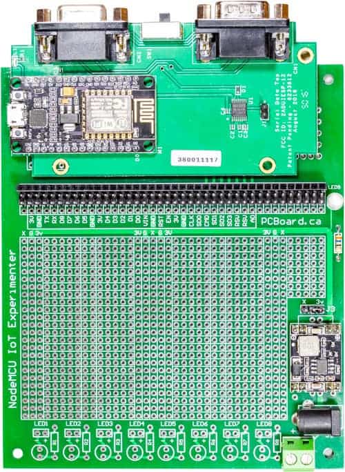
The board offers over 1,000 plated-through holes on the prototype surface, mounting for eight status indicator LEDs along with dropping resistors and a power indicator LED. The prototyping area offers power busbars for the Ground (G), +3.3V (3V) power rail, and a third rail X. The third rail can be used for external voltages such as a 5V rail.
Interfacing to the NodeMCU is through a series of headers that extend each pin of the NodeMCU to rows of four headers. Each port is labeled to identify matching pins from the NodeMCU. The header area is located below the NodeMCU using standard 40-pin headers allowing for versatility in interfacing for sockets or header pins.
For more information about the NodeMCU IoT Experimenter, visit the support page.
Are you interested in purchasing NodeMCU IoT Experimenter, either a partial or full kit of parts? Visit the Online Store for the NodeMCU IoT Experimenter or other NodeMCU and Arduino accessories.